IPC Class 3 PCB Assembly: Inspection, Lead Time and Cost Factors
- zeng, liuyan
- 848 reads
Class 3 assembly depends on tighter workmanship limits, inspection matched to each joint, and clear plans for first articles, testing and traceability.
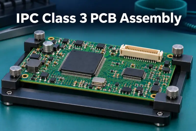
IPC Class 3 assembly puts the focus on whether each connection can meet the product’s required acceptance criteria, including joints that optical inspection can’t see. For boards with fine-pitch leads, through-hole connectors and BGAs, that means specifying inspection methods alongside the workmanship class. EBest Circuit says its engineers review designs before production and provide a design-for-manufacture report and a bill of materials (BOM) optimization list.
The company describes a turnkey planning reference of 10–12 business days from confirmed files and purchase order. The actual ship date also depends on the complete parts kit, first-article approval and test readiness. Those dependencies matter when a board needs hidden-joint inspection or functional testing before release.
Where Class 3 requirements apply
Products that may call for IPC Class 3 include flight-control computers, ventilator controllers, patient-monitor alarm boards, airbag control units, railway signaling interlocks, protective relay boards, industrial safety interlocks and subsea instrument controllers. Their common design concern is reliable operation when a fault could have serious consequences or when the board must respond on demand.
The product owner sets the required class for each assembly. A patient monitor’s alarm board and an accessory used to service the same monitor, for example, can have different acceptance requirements. A Class 3 bare PCB also does not automatically make the populated assembly Class 3: the components, placements, solder joints and finished workmanship need their own assembly specification.
Placement limits can change acceptance
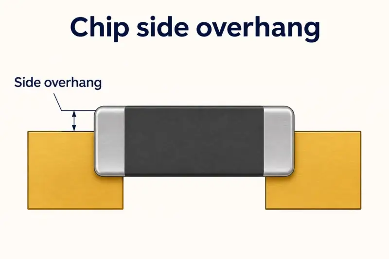
A placement offset that falls within Class 2 criteria can exceed the Class 3 limit. In an example based on IPC-A-610E §8.3.2.1, a rectangular chip has a 0.40 mm termination on a 0.50 mm pad. The narrower dimension, 0.40 mm, is the reference width for assessing side overhang.
| Side overhang criterion | Class 2 | Class 3 |
|---|---|---|
| Maximum as a percentage of reference width | 50% | 25% |
| Maximum for the example chip | 0.20 mm | 0.10 mm |
| At a measured 0.15 mm | Within limit | Exceeds limit |
That distinction can affect acceptance even if the board powers on. The example uses revision E; production decisions depend on the revision named in the order and the criteria that apply to the actual termination.
Match inspection to the connection
J-STD-001 covers soldering materials and processes, while IPC-A-610 supplies workmanship criteria for evaluating the completed assembly. EBest Circuit describes inspection plans that address each joint type: optical checks for gull-wing lead overhang, joint width and heel fillet; through-hole checks for barrel fill, wetting and land coverage; and X-ray checks for BGA alignment, bridges and void patterns.
Optical inspection can reveal a displaced exposed lead or a bridge between visible pins. A through-hole connector’s surface fillet shows wetting at the board surface, but it does not by itself establish how much solder fills the barrel when that area is hidden from view.
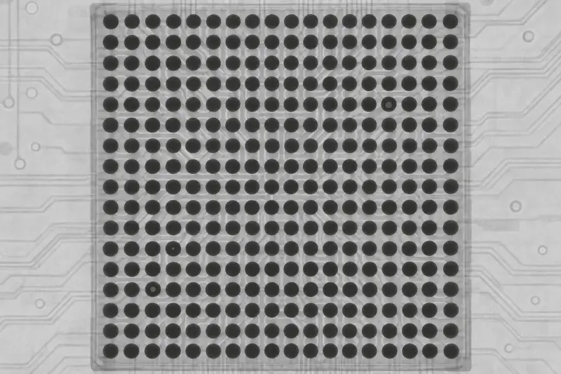
BGA connections need a method that can see beneath the package. X-ray can reveal a bridge or void pattern, while functional testing checks whether the processor boots and communicates under the specified conditions. If both are required, the inspection plan should identify the packages, X-ray acceptance criteria, sampling approach and records to retain for each lot or serial number.
Schedule and cost follow the build plan
Parts can be sourced while bare-board fabrication is underway, but the assembly line still needs the full kit. A late-arriving processor can delay the start of surface-mount assembly; a missing through-hole connector can hold shipment after that stage is complete. If the customer must approve a first article before the rest of the lot runs, that review adds a scheduling dependency. A test fixture can be prepared during fabrication, but boards may wait if the fixture or released firmware arrives late.
For repeat builds, an unchanged board revision and test procedure may allow the existing setup to be reused. Quotes should distinguish the first-article ship date from the tested production-lot ship date.
Cost also separates into setup work and per-board work. A stencil or dedicated fixture may serve multiple batches if the design remains compatible. The source gives a simple example: spreading the same fixture charge across 200 boards instead of 20 reduces its per-board share to one tenth. Components and assembly time recur for every unit; through-hole power connectors require a post-surface-mount soldering operation when the specified process calls for it.
Inspection scope affects the comparison between quotes. Reviewing one BGA on every board and retaining an image linked to its serial number takes more work than sampling from a lot. Two quotes for the same BOM may therefore include different inspection coverage and records.
Example: 12-layer diagnostic device
A Mexico-based medical device manufacturer commissioned a 12-layer HDI board for a portable diagnostic device. The design combined 01005 components and BGAs, with IPC-A-610 Class 3 workmanship and a project-specific BGA void target of 3% or less.
The build required control of solder-paste deposits before reflow because 01005 components leave little pad area. After reflow, 3D X-ray was used to examine voiding beneath the BGAs against the customer’s target. Manufacturing execution system records captured process history so the customer’s quality team could trace an individual board.
Define the order before production
For a quote, EBest Circuit asks for board and assembly files such as Gerber or ODB++, a BOM with manufacturer part numbers, placement data and the released assembly drawing. The order should identify applicable standards and revisions, critical BGAs by reference designator, X-ray and functional-test requirements, quantities, customer-supplied parts, and target dates for first articles and completed lots.
Acceptance should follow the revision invoked by the controlling order and drawing. If those documents disagree, the discrepancy needs resolution before production. Prototypes and production boards can have different classes when the project documents state that explicitly; a prototype accepted to Class 2 does not by itself establish that a production build meets Class 3 criteria.
Inspector training credentials describe a person’s qualification within its stated scope. Shipment evidence needs to relate to the supplied assemblies, their revision and the order’s acceptance requirements. Similarly, an alternate component can change termination geometry, moisture handling or reflow limits even when its electrical function is equivalent, so engineering review may call for updated process settings, inspection programs or first-article checks.
EBest Circuit says it supports prototypes and small batches, offers a 1.5-week turnaround for eligible builds when parts and test requirements are ready, and can retrieve recorded material and product-batch details within five seconds. For planning, the useful inputs are the first-article quantity, target date and defined inspection coverage; together they determine whether the requested ship date is feasible.