Designing Precision Current Sources and Sinks with GreenPAK Mixed-Signal ASICs
- altium-designer
- 580 reads
Current regulation depends on load voltage and circuit headroom. GreenPAK combines adjustable current control with sensing, timing and logic functions.
Current regulation gives a circuit control over the load current even as the load voltage changes. That makes it useful for sensor excitation, LED drive and capacitor ramp generation, where a fixed voltage alone won’t set the desired behavior. The design’s limits come down to the required current, the load’s voltage range and the headroom available to keep the regulating circuit in control.
GreenPAK offers one way to combine current regulation with application-specific monitoring and sequencing. Its configurable analog and digital blocks can form a current source or sink, with an adjustable setpoint and other system functions in the same device. The trade-off is that the design must fit the device’s available analog resources, timing blocks and pins.
Current regulation and voltage headroom
A current source aims to hold current constant as load impedance changes. Practical circuits can do this only within a voltage range: the supply must cover the voltage across the load, plus the voltage and other losses required by the regulator, wiring and connections. Once that headroom runs out, the circuit can no longer maintain the set current.
The relationship is direct. At 1 mA, a 1 kΩ load requires 1 V across it; a 5 kΩ load requires 5 V. A design therefore needs to check its maximum load voltage as well as its current accuracy. A current loop can be well behaved within its operating range and still fail to regulate when the supply cannot provide enough voltage.
Different circuit approaches close the feedback loop in different ways. Switching current-mode regulators can use PWM regulation, while other designs may rely on emitter or source degeneration, or transistor and diode clamps. The method changes, but the practical requirement remains: the circuit needs sufficient voltage headroom to control current.
Current mode is useful when the current itself carries the measurement or control information. An RTD, for example, can be excited with a defined current so its resistance produces a measurable voltage. LED drivers regulate current as forward voltage shifts with temperature and device variation. For a capacitor, constant charging current produces a linear voltage ramp, following dV/dt = I/C.
Choosing a current sink and sense location
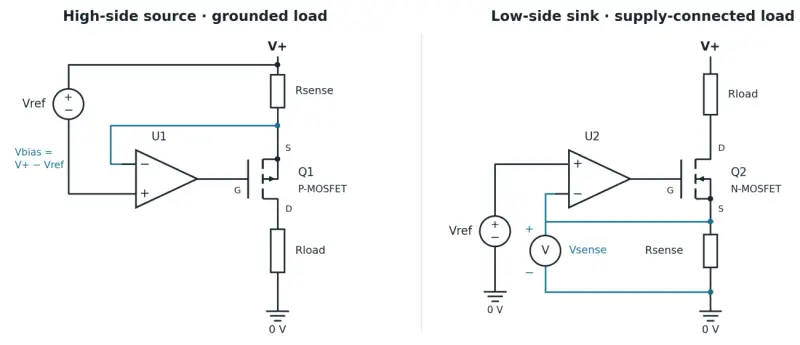
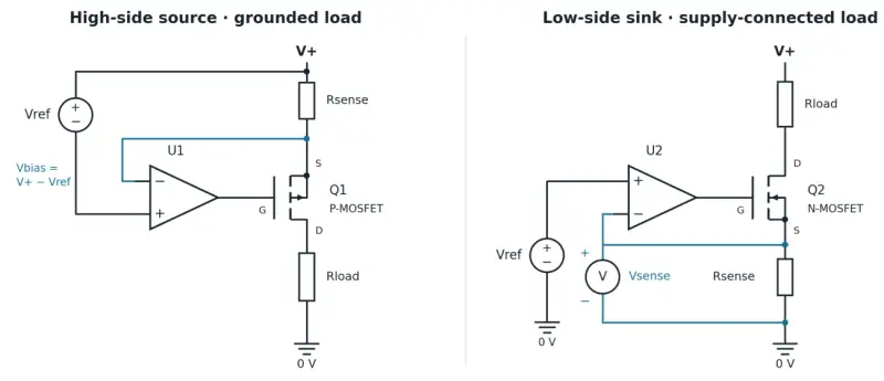
A current sink controls how much current it draws through a load. A transistor’s conduction is adjusted using feedback from a sense resistor, which develops a voltage corresponding to the current. The resistor and control loop can sit on the high side or low side, depending on how the load connects to its supply and ground.
A load that must remain grounded generally calls for high-side regulation. If the load connects to the supply, regulation may instead fit in its return path. That low-side arrangement is straightforward, but its sense resistor lifts the load’s ground terminal above the 0 V reference by the sense voltage. Any circuit measuring the load voltage or sharing its return must account for that offset. Circuits that need the same reference should connect to the high-side terminal of the low-side sense resistor.
That reference detail affects system behavior, not just the current loop. A voltage measurement made against the wrong side of the resistor will include the sense voltage as an offset. Designers should therefore decide where the load and its associated circuitry take their reference before settling on high-side or low-side sensing.
Dedicated devices and system control
Dedicated ICs can handle the current-regulation function. Analog Devices’ LT3092 is a programmable current source whose setpoint is established with two external resistors. Texas Instruments’ TLC5916 provides eight regulated sink outputs for LED loads. These parts illustrate two different integration choices: a configurable source and a multi-output sink device.

Current regulation may be only one part of the required behavior. Supply qualification, startup delay and enable interlocks can call for additional control circuitry around a dedicated regulator. GreenPAK combines configurable analog functions with comparators, logic and timers, allowing designers to build some of that application-specific behavior alongside the current-control loop.
GreenPAK source and sink implementations
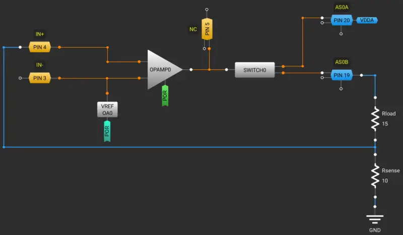
The SLG47004 example forms a current source with an internal op amp and MOSFET. OPAMP0 drives SWITCH0, configured as a P-channel MOSFET in Analog Switch mode. The amplifier compares a reference with feedback from the external sense resistor, closing the loop around the load. The nominal load current is Vref/Rsense.
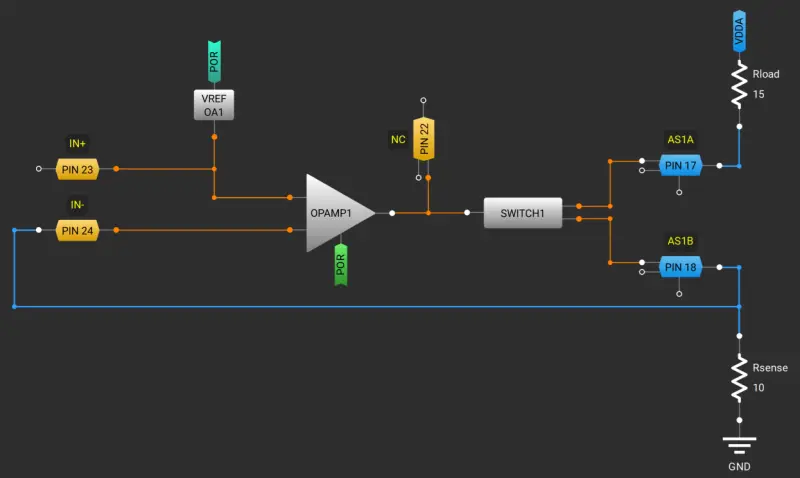
The reference comes from an internal source and can be adjusted in real time over I2C, which changes the current setpoint. In the corresponding sink arrangement, OPAMP1 drives SWITCH1 configured as an N-channel MOSFET. The programmable reference feeds the noninverting input, while sense feedback reaches the inverting input; current returns to ground through the sense resistor.
Both examples offer selectable amplifier bandwidth. Their reference can come from the internal 2.048 V source or from VDDA through a six-bit divider. I2C adjustment changes the reference and, in turn, the current setpoint. The available range and behavior still depend on the surrounding load, sense resistor and circuit headroom.
Combining current control with other functions
The appeal of a configurable mixed-signal device extends beyond changing a current setpoint. GreenPAK can also bring together ADC voltage measurements, comparator thresholds, logic processing through lookup tables, and digital functions such as timing, delay and counting. That combination can reduce the number of separate devices when a sensing interface or power design needs both current regulation and control logic.
Renesas’ Go Configure development suite lets engineers set comparator thresholds, qualification logic, delays and output behavior. Simulation and development hardware can be used to evaluate the resulting sequence, including early requests and interrupted settling. Device choice depends on the number of independently controlled enable outputs and the analog, timing and pin resources each one requires.
The design decision is therefore broader than choosing a current value. Check the load’s full voltage range and the regulator’s headroom, choose a sense location that fits the load’s reference needs, then confirm that the selected device has the analog and control resources for the complete sequence. GreenPAK’s value is strongest when current regulation and those surrounding functions belong in the same design.