Smart Electrical Panels Need Dedicated Sensors for Leakage and Load Monitoring
- IoT.Business.News
- 869 reads
Energy meters miss feeder faults and milliamp leakage. Sensor choice, installation and edge processing determine whether a smart panel can explain trips.
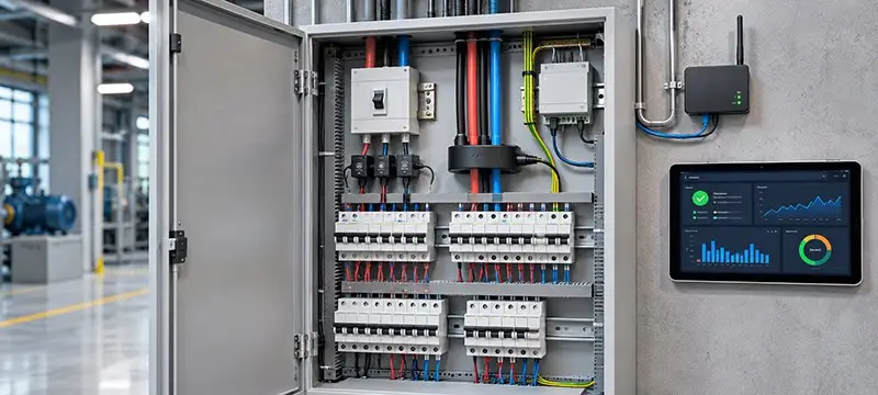
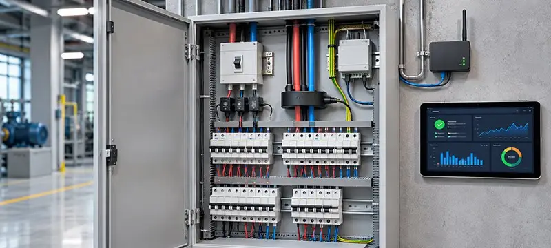
A smart panel can report total energy while leaving operators unable to identify which feeder caused a trip. A multifunction meter on the incoming supply and a cloud dashboard full of kilowatt-hour charts may show how much a building used, but not whether a particular circuit has developed earth leakage or how that leakage changed over time. That gap matters in facilities where a residual current breaker can interrupt refrigeration, motors or other critical loads.
Useful monitoring starts with the measurement point. Current sensors must match the signal being measured, and earth leakage needs a sensing arrangement designed to distinguish a small residual current from the much larger normal load. The gateway and dashboard can make those measurements easier to interpret, but they cannot recover a signal the panel never captured.
Choose the sensor for the current and the job
Five technologies cover most current sensing needs in distribution panels: shunt resistors, Hall-effect sensors, standard current transformers (CTs), Rogowski coils and zero-sequence current transformers (ZCTs). The first four measure load current, with varying ability to handle AC, DC, high current and fast-changing waveforms. A ZCT measures the imbalance across the live conductors to detect residual current.
A shunt is a low-value resistor installed in the current path. The voltage across it tracks current, making shunts useful for AC and DC at low to moderate levels, including battery systems and compact meters. They have no inherent galvanic isolation, and heat dissipation becomes a concern at high current.
Hall-effect sensors use a semiconductor element to measure magnetic fields produced by current. They can handle AC, DC and mixed waveforms, which suits applications such as PV and battery inverters, EV chargers and DC feeders. They require a power supply, and offset and temperature drift can affect readings.
Standard CTs rely on magnetic induction and are commonly used for AC feeder and branch metering, including tenant sub-billing. They do not measure DC, and excessive current or DC bias can saturate the core. Rogowski coils use an air-cored winding, so they do not saturate magnetically. Flexible versions can wrap around large busbars during retrofit work and suit large or fast-changing AC currents, including harmonics. They need an integrator and are generally less suitable for very small currents.
A ZCT has a different purpose: phases and neutral pass together through one magnetic core. In balanced operation, their magnetic effects cancel. Any residual current creates a net signal for the sensor to detect. This makes ZCTs suitable for earth-leakage monitoring, insulation trending and residual current monitoring systems. They do not measure individual load current; conventional versions are designed for AC residual current.
| Technology | Best suited to | Typical limitation |
|---|---|---|
| Shunt resistor | AC and DC current at low to moderate levels | No inherent isolation; heat at high current |
| Hall-effect sensor | AC, DC and mixed waveforms | Offset and temperature drift; needs power |
| Standard CT | AC current at mains frequency | AC only; can saturate |
| Rogowski coil | Large or fast-changing AC current and harmonics | Needs an integrator; weaker fit for very small currents |
| ZCT | Small residual current across live conductors | Does not measure individual loads; conventional versions are AC only |
A panel that needs both load visibility and leakage detection will typically combine sensor types. The right mix depends on which circuits need measurement and what faults or operating changes the monitoring system must reveal.
Why feeder CTs cannot reliably calculate milliamp leakage
It may seem possible to estimate leakage by adding phase and neutral readings from the CTs already installed on a feeder. In an ideal balanced circuit, the vector sum of current through all live conductors is zero. Current that returns by another path can create a residual signal. In practice, subtracting large measurements to find a tiny difference puts tight demands on sensor accuracy and matching.
Consider a 30 mA leakage current on a 400 A feeder: that residual is 0.0075% of the CT’s rated current. A class 0.5 metering CT has a permitted current ratio error of 0.5% at rated current under specified conditions, equivalent to 2 A at 400 A. Accuracy also varies with operating current, and errors typically rise at low percentages of the rated value. When measurements from several CTs are combined, their ratio and phase errors can outweigh the leakage signal.
The result can look like a changing fault when the readings are responding to ordinary load variations. For example, calculated leakage may appear to rise each morning as building loads start, even if insulation condition has not changed. A ZCT avoids this subtraction problem by measuring the net magnetic effect of the conductors together. Properly designed units can detect leakage in the milliamp range, though the exact sensitivity depends on the model.
Match residual-current sensing to the waveform
Power electronics can produce residual currents that are not clean mains-frequency sine waves. Variable-speed drives, EV chargers, PV inverters and switch-mode power supplies may introduce pulsating DC, smooth DC or high-frequency components. A sensor designed only for AC may not capture these reliably.
Residual current protective devices are commonly categorized as types AC, A, F and B according to the fault-current waveforms they can detect. A sensor’s specifications do not automatically align with those categories. Check its stated waveform coverage, measurement range and frequency response against the equipment on the monitored circuit. Installations with substantial power electronics may need fluxgate sensing or a dedicated residual current monitoring solution if conventional core-balance CTs cannot handle the expected DC components.
Monitoring and protection also serve separate functions. A residual current monitor reports values and can raise alarms; a residual current protective device disconnects a circuit when required. IoT monitoring can provide earlier indications and diagnostic data, but it does not replace required electrical protection.
Measure temperature and voltage where they add context
Current alone may not reveal a deteriorating connection. A terminal can run hotter than neighbouring connections after years of thermal cycling, even while the load current appears normal. A temperature sensor near a terminal or busbar joint adds information that a current channel cannot provide. Wireless sensors can simplify retrofits by reducing measurement wiring inside the enclosure, but their installation and communications still need to suit the electrical and environmental conditions.
Voltage readings add another essential part of the picture. Combined with current and phase relationships, they let a metering module calculate real power, apparent power, power factor and energy. Humidity sensors, arc detection and other environmental measurements may also help, depending on the site. Installing every available sensor does not make every panel more useful; measurements should support an operational need.
Move measurements from the panel to the platform
A common architecture sends sensor signals to a measurement module, which calculates RMS values, energy use and, where supported, residual current. The module communicates with an edge gateway over Modbus RTU on RS-485, a long-established industrial serial interface. The gateway then forwards selected data to an IoT platform, often using MQTT or HTTPS over an IP network.
Processing at the gateway can make the data more useful. It can filter routine samples, flag anomalies, trigger alerts and retain a detailed window of measurements around an electrical event. That record can help teams investigate a trip without transmitting every sample continuously. Local alarm handling and data buffering also matter when a network or cloud service is temporarily unavailable.
Where wired networking is unavailable, the choice of wireless link should reflect the reporting interval, coverage, latency, power supply and amount of data. LoRaWAN can suit small periodic measurements and alarm messages, but its limited data rate and duty-cycle constraints make large transfers impractical. NB-IoT supports cellular links for relatively small data volumes; LTE Cat 1 bis can serve applications that need more throughput or more frequent communication.
Metal enclosures can weaken radio signals. Antenna placement and coverage checks belong in the design process, because a gateway that communicates with the cabinet open may struggle once the door is closed. Network security also needs attention: use authenticated communications, encryption where applicable, controlled access to configuration interfaces, secure firmware updates and appropriate network segmentation. Device lifecycle management helps keep those controls in place over time.
Check range, output and installation before ordering
Choosing a CT based only on the breaker rating can leave the sensor operating for most of its life far below its nominal current. Accuracy at the lower end of the range may matter more than the headline specification, depending on whether the goal is energy billing, operational trending or fault detection. Check the required accuracy class across the expected operating range.
Output type must suit the measurement module. Conventional CTs with 1 A or 5 A secondaries must not be left open-circuited while the primary is energized. Some monitoring systems use voltage-output or millivolt-output CTs, but the sensor and module still need to be compatible, and installation must follow the manufacturer’s requirements.
For residual monitoring, verify sensitivity at the intended alarm threshold rather than relying on a nominal sensor rating. The aperture must fit all live conductors belonging to the monitored circuit, including the neutral when present, while leaving the protective earth conductor outside. Conductor position also matters: significant asymmetry inside the aperture can increase errors, particularly at high load current. Circuits serving drives, chargers or inverters need sensors with suitable DC and frequency response.
Installation access influences the choice of core. Split-core sensors can be fitted around existing cables without disconnecting them, which can help in occupied buildings. Closed-core designs avoid the joint in a split core, but generally require conductors to be disconnected or routed through the sensor. Neither format guarantees better low-current accuracy; compare the specifications of the particular models under expected operating conditions. Examples of available form factors and specifications appear in the zero-sequence current transformer range.
Commission the sensors as part of the system
Several common wiring errors can undermine the data. Routing the protective earth conductor through a residual current sensor may let fault current cancel some or all of the measured imbalance. Leaving the neutral outside the core can make normal load current appear to be leakage and trigger an alarm. Mounting a load CT backwards can produce negative power readings, making an installation that consumes energy look as if it is exporting it.
Commissioning should therefore validate wiring, polarity and expected readings, not just confirm that data reaches the dashboard. A site visit to correct a basic installation error can cost far more than the sensor itself. Edge analytics can help identify patterns and prioritize investigation, but reliable conclusions still depend on the physical measurements being appropriate and correctly installed. The practical test of a smart panel is whether it can connect a trip or abnormal trend to useful evidence from the circuit.