Build Keyence VT Studio HMIs with PLC Tags, Alarm Logs and Simulation
- Michal Gumulak
- 565 reads
Configure writable controls, read only indicators, PLC driven alarms and VT/KV Studio simulation in a practical Keyence HMI workflow.
Keyence VT Studio’s HMI tools become more useful when screens, PLC tags, alarms and simulation are treated as parts of one application. With a VT Studio project already connected to a Keyence PLC and its KV Studio tags imported, the next steps are to build operator controls, show live values, define alarm messages and check the PLC–HMI interaction in simulation.
Build screens around the PLC tags
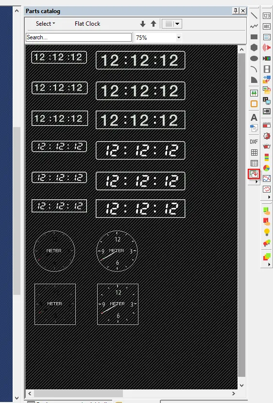
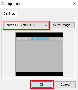
Open “Screen 1” from the project tree and place a “Call up screen” object so it covers the full screen area. In its dialog, select the existing screen intended to serve as the background. This lets the new screen provide a base for additional controls and displays.
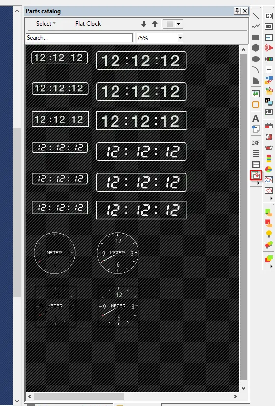
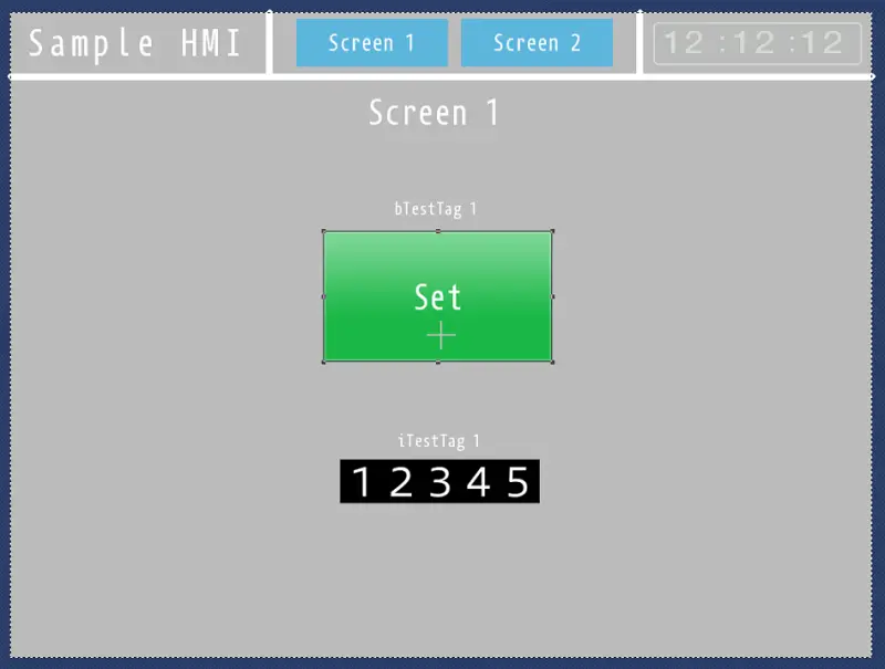
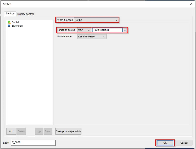
For operator input, use the tags that have read and write permissions. Add a “Switch” object for the Boolean tag and a “Numeric entry field” for the integer tag, then add labels so operators can identify each control. The switch’s properties determine what PLC bit it changes: select “Set bit” as its function, and choose the writable Boolean tag as the “Target bit device.” In the example, that tag is “bTestTag1.” Set “Switch mode” to “Set momentary” for this configuration.
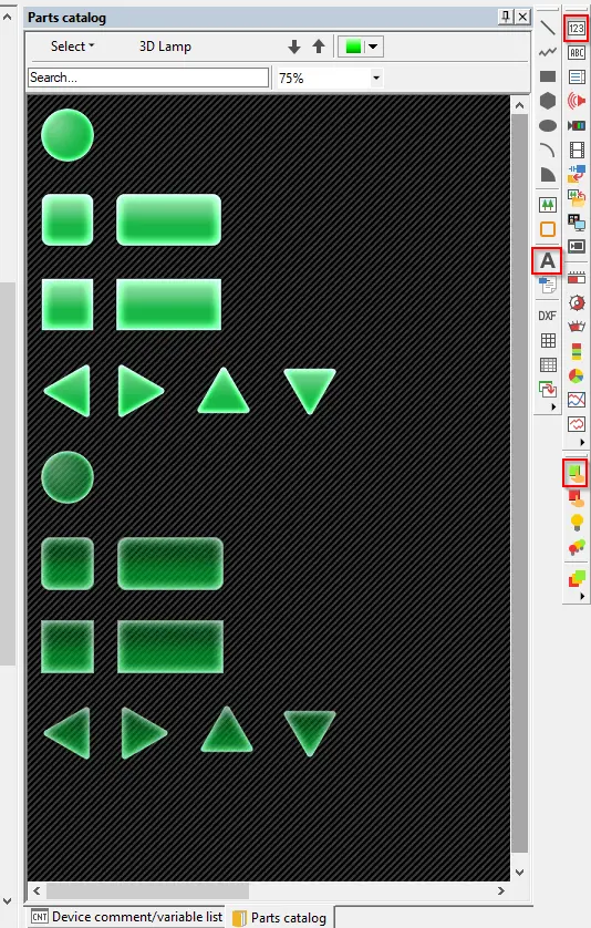
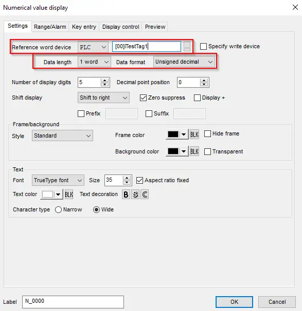
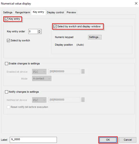
Set the numeric field’s “Reference word device” to “iTestTag1.” Its data format needs to match the PLC tag, so check that setting as well as the tag assignment. To make the field usable on a panel without a physical keyboard, open the “Key Entry” tab and enable both “Key entry” and “Select by switch and display window.” The latter option provides a touch keypad in a pop-up window for entering a value.
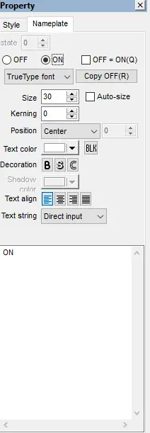
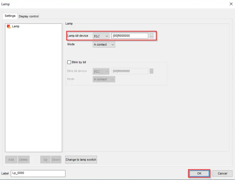
Screen 2 can present read only data. Add a “Lamp” for a Boolean status and a “Numerical value display” for an integer, then label the indicators and give the screen a title. In the Lamp’s properties, configure the nameplate and distinct On/Off appearances to reflect the Boolean state. Assign the read only tag “bTestTag2” to “Lamp bit device.”
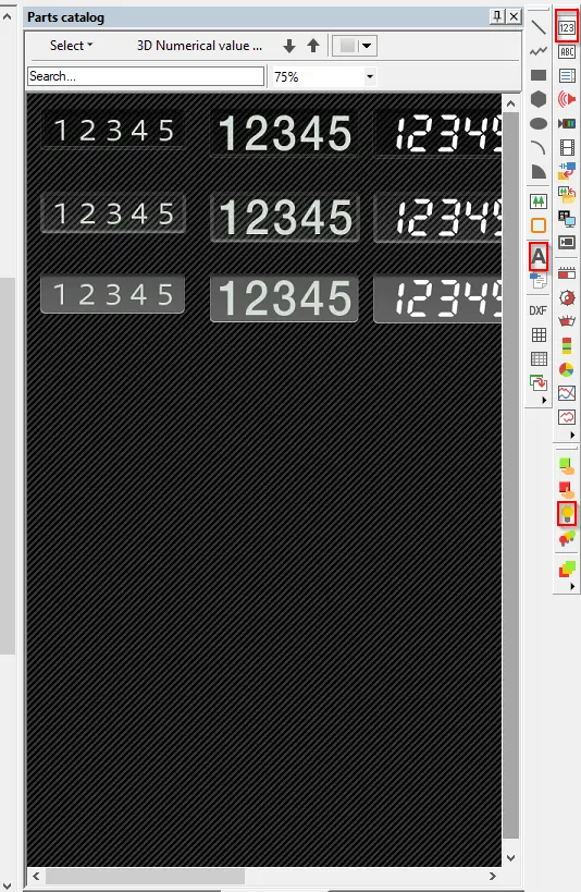
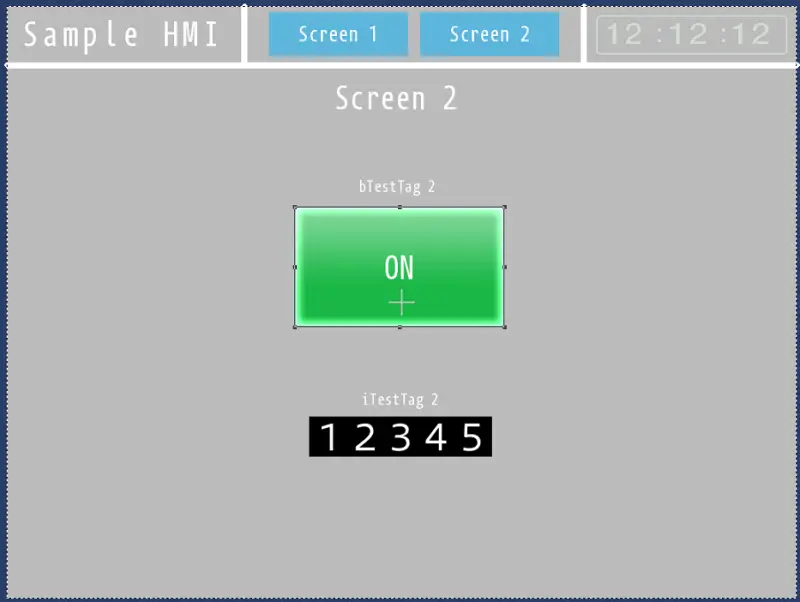
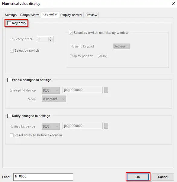
For the numerical display, use the same settings approach as the entry field, but set its reference to “iTestTag2.” In “Key Entry,” leave “Key entry” disabled. This keeps the value visible without presenting it as an operator input. Taken together, these two screens establish a clear division between values operators can change and data they can observe.
Map PLC memory bits to alarms
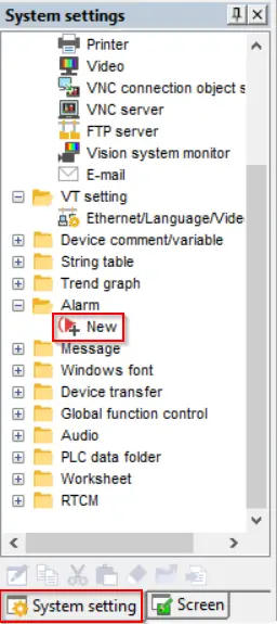
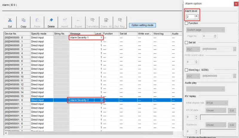
VT Studio’s alarm configuration assigns messages to bits in PLC data memory. Start under “System setting” > “Alarm,” choose “New,” and create an Alarm ID. The key setting is “Number of devices”: each device corresponds to a data memory word, and each bit in that word can activate a separate alarm while it is enabled.
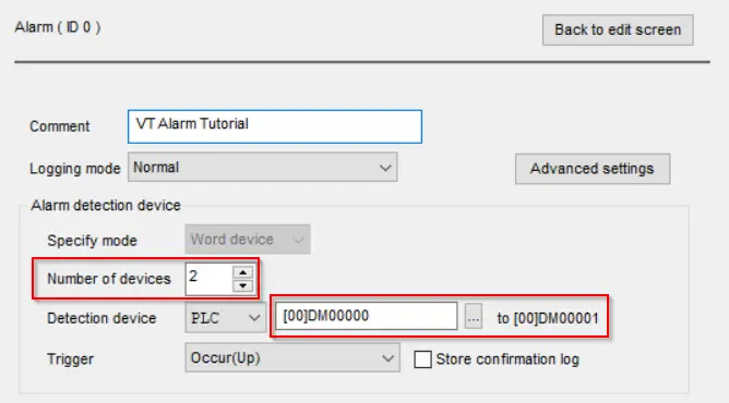
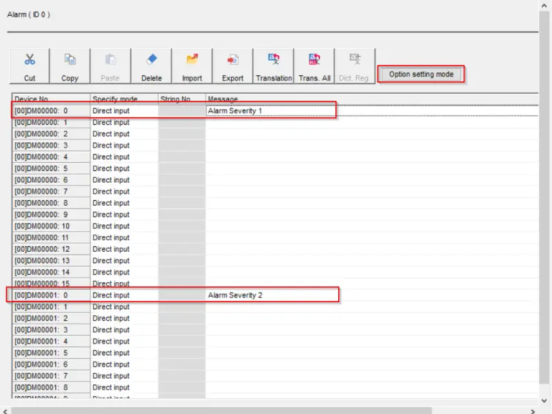
Set the number of devices needed for the application. The example uses two, which provide 32 message positions in total. Open the “Message” tab beneath the new alarm folder and enter text against the relevant bits; the example assigns messages to bit 0 in each word. “Option setting mode” exposes further configuration, including bit settings, alarm level and audio playback. The example changes the level for one alarm.
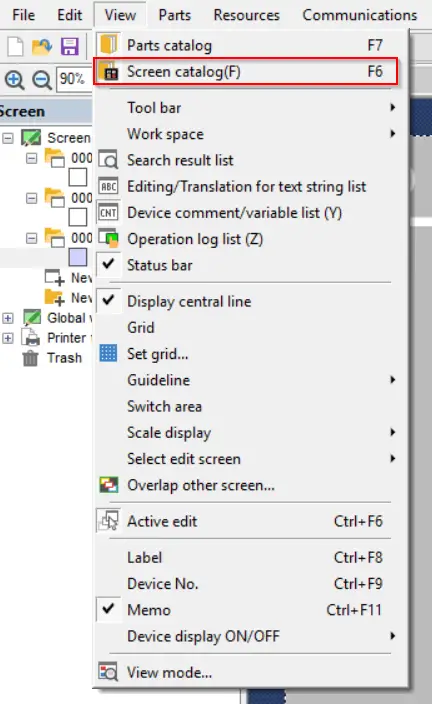
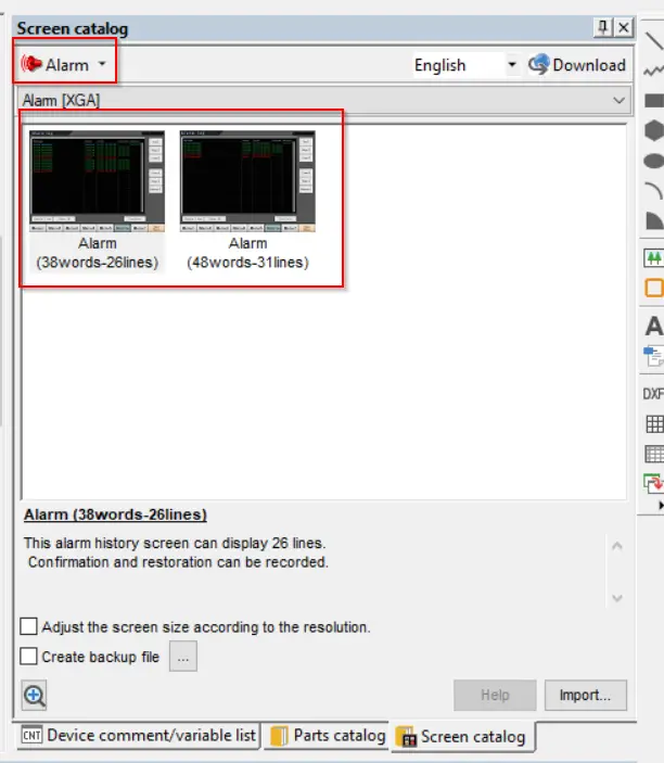
An alarm activates when its corresponding PLC memory bit is set, and remains active while that bit is high. To show alarm activity on the HMI, VT Studio’s “Screen catalog” offers prebuilt screen layouts. Find it under the “View” settings tab, choose “Alarm” in the dropdown, and drag a suitable screen into the project.

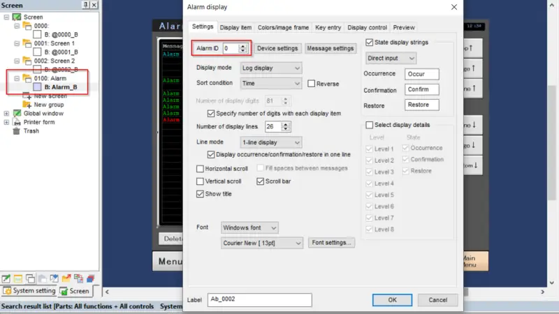
Open the alarm table on that screen and set its “Alarm ID” to the ID configured earlier. Adjust the remaining table settings to suit the application, then link the alarm screen into the rest of the HMI navigation. The result is an alarm log page connected to the PLC’s memory bits and the messages configured for them.
Test PLC and HMI behavior together
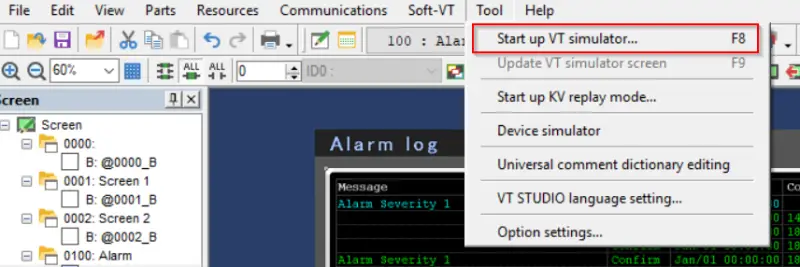
VT Studio and KV Studio can run together in simulation, allowing the screens and PLC logic to be exercised as an interacting system. Before starting, open both projects and import the current KV Studio tags into VT Studio. Then select “Tool” > “Start up VT simulator…” and choose “KV STUDIO” on the startup page.
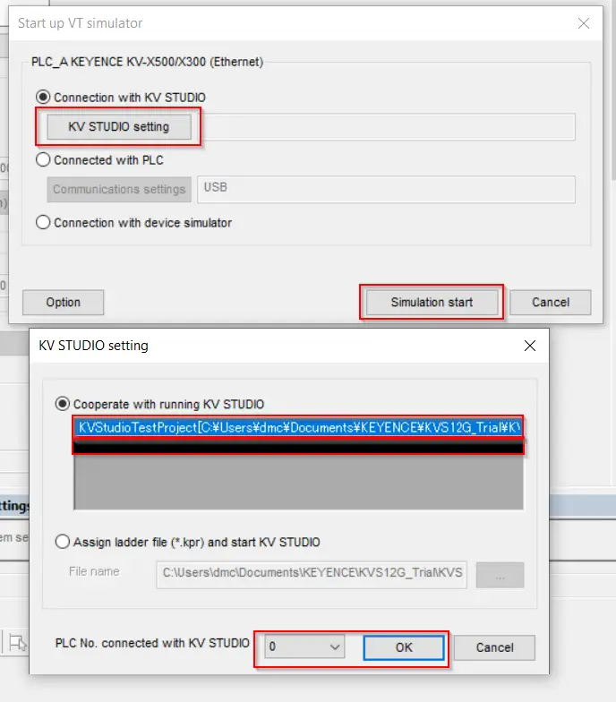
Select the KV Studio project to run and check that the PLC number matches. Choose “OK,” followed by “Simulation start.” KV Studio opens and prompts for Run mode; confirm to enter its simulator mode. VT Studio then displays a simulated HMI. Controls, displayed values and PLC logic can be checked through their interaction in this setup.
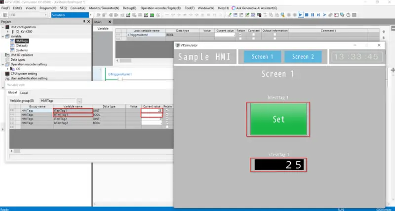
These functions form a practical starting point for a working HMI: writable Boolean and integer controls, read only status displays, bit driven alarms and a simulation path for checking behavior before using physical hardware. As screens grow, keeping tag permissions, data formats and alarm bit assignments aligned with the PLC will help maintain a predictable operator interface.