Getting Started with Keyence VT Studio: PLC Tags, HMI Setup and Screen Navigation
- Michal Gumulak
- 948 reads
Set up a VT Studio project, import KV Studio tags, configure PLC communication and build a reusable screen layout with page navigation.
A useful VT Studio project starts with three pieces in place: the right panel model, a defined connection to the PLC, and a screen structure that can grow without repeating the same layout work. Keyence’s VT Studio programs its VT series HMIs; this walkthrough pairs it with a Keyence KV series PLC configured in KV Studio. VT Studio also offers PLC selections from other manufacturers and a general Modbus TCP option for controllers that support that protocol.
Choose the panel and PLC before drawing screens
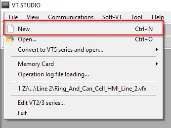
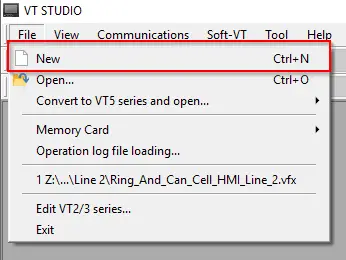
Create a project from File > New, or use Ctrl+N. The first dialog asks for the VT series and panel model. Choose the hardware the project is intended to run on, then set whether to use a slide tab and where it should appear. Those choices establish the project’s target configuration before you start laying out controls.
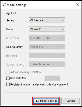
Open PLC model settings to choose the controller connection. The list includes manufacturers such as Rockwell, Siemens and Mitsubishi, alongside Keyence. For controllers that can communicate over Modbus TCP, the general protocol option provides another connection path. VT Studio’s Multitalk function can connect to multiple controllers, including controllers of different types, which can be useful when an HMI needs data from more than one device.
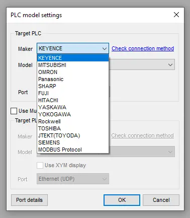
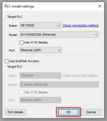
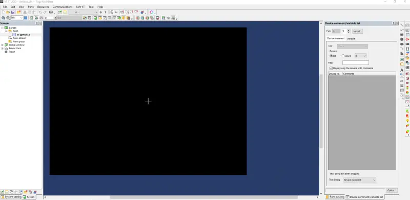
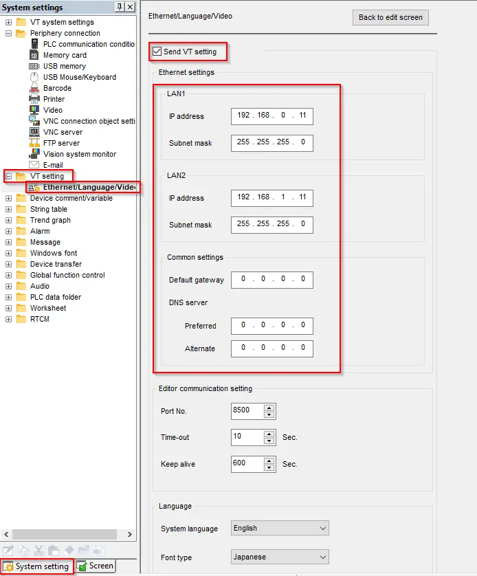
This example uses a Keyence KEV-X500/X300 PLC platform. After selecting the target, confirm the setting to open the project editor. Before building screen objects, configure the panel’s network settings: go to VT setting > Ethernet/Language/Video and enable Send VT setting. That option allows you to set the IP addresses for the HMI panel ports.
Prepare the KV Studio variables for HMI use
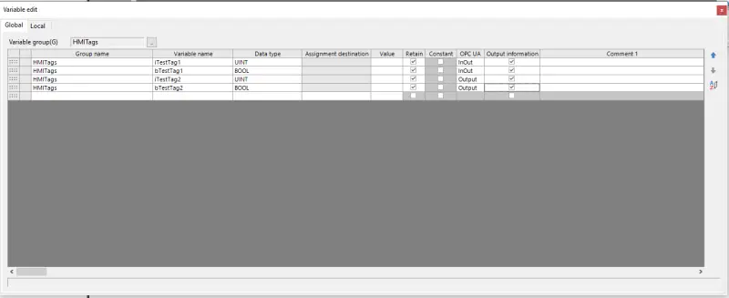
For a KV series controller, decide which PLC variables the HMI needs and configure those variables in KV Studio before importing them. In the Variable Edit viewer, set each relevant variable’s OPC UA access to Output for read access or InOut when the HMI needs read/write access. The Output Information box must also be checked. Save the KV Studio project and leave it open while returning to VT Studio.
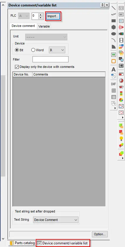
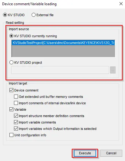
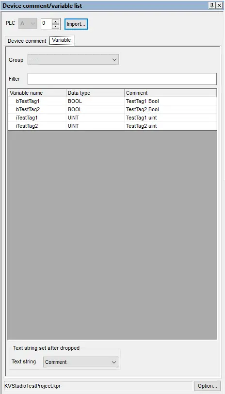
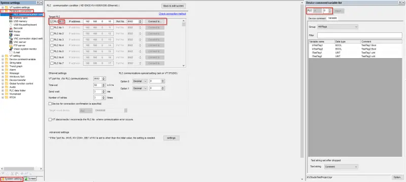
In VT Studio, open the Device comment/variable list tab and choose Import. If the KV Studio project is open, select it under KV STUDIO currently running. Otherwise, browse for it through KV STUDIO project. Choose the project and run the import. The configured variables should then appear in the list’s Variable tab.
Complete the connection setup under System setting > Periphery connection > PLC communication condition. Check that the target PLC address is correct and matches the number used for the imported controller. Keeping the PLC selection, address and imported variables aligned gives the project a consistent basis for building controls that use those variables.
Build a reusable background and navigation
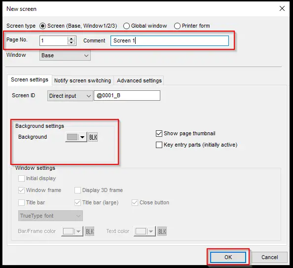
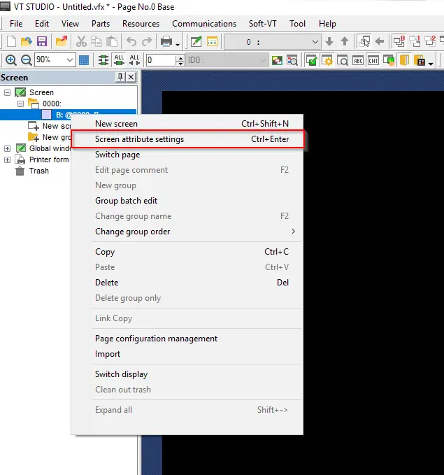
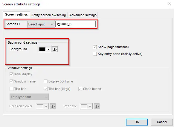
A background screen gives the other pages a shared frame. It can hold elements such as a header, footer, title or navigation controls, so the same layout does not need to be recreated on every screen. In the project editor, right-click the screen and open Screen attribute settings. There you can review its Screen ID and choose a background color.
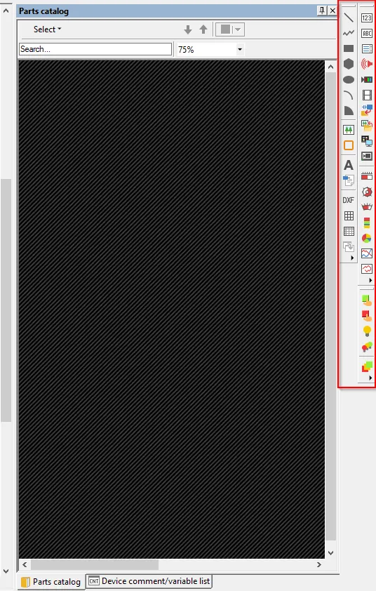
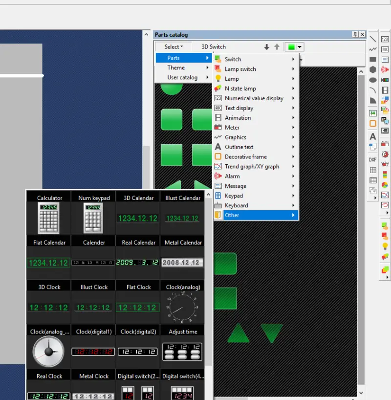
Use the drawing tools and text objects to create a header, then add buttons for page navigation. The parts catalog includes a clock that can be placed in the header; other available parts provide additional options as the screen needs develop. The example layout uses a title, two navigation buttons and a clock.
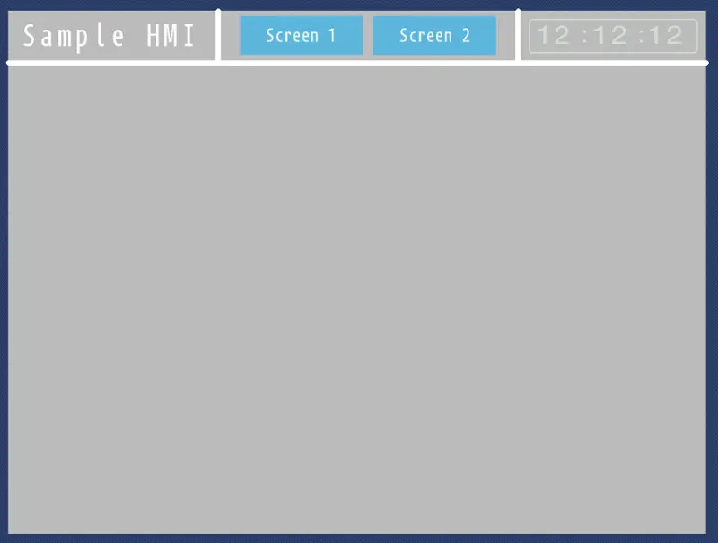
Create two more screens from the project navigation area using New screen. Give each a unique Page No. and a name, then set its background color to match the shared layout. The unique page numbers matter because the navigation buttons must point to the intended destination.

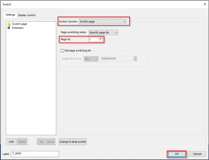
Return to the background screen and open the settings for the first navigation button. Change its Switch function to Switch page, then select the Page No. assigned to the first new screen. Repeat for the second button, choosing the other page number. This connects the shared navigation to the pages created in the project.
At this stage, the project has a selected VT panel, a configured PLC connection, imported KV variables and a basic multi-screen layout. The next design work can build on that structure by adding controls tied to the variables and refining each page for its intended operation.